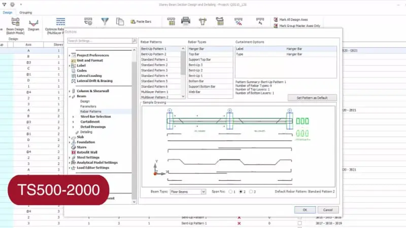
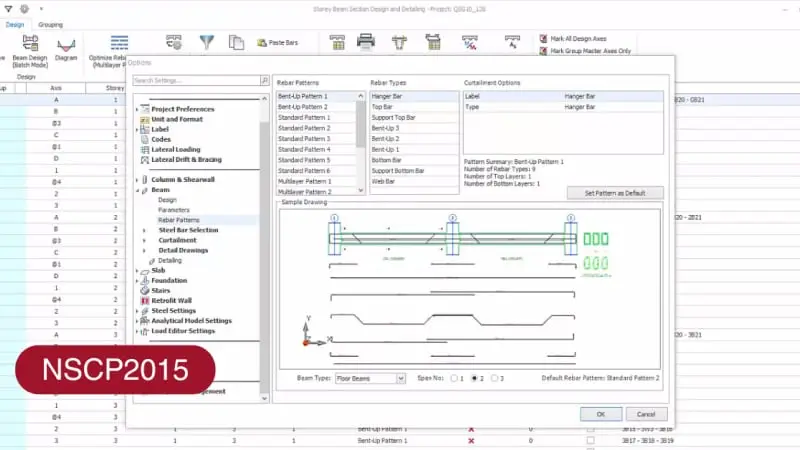
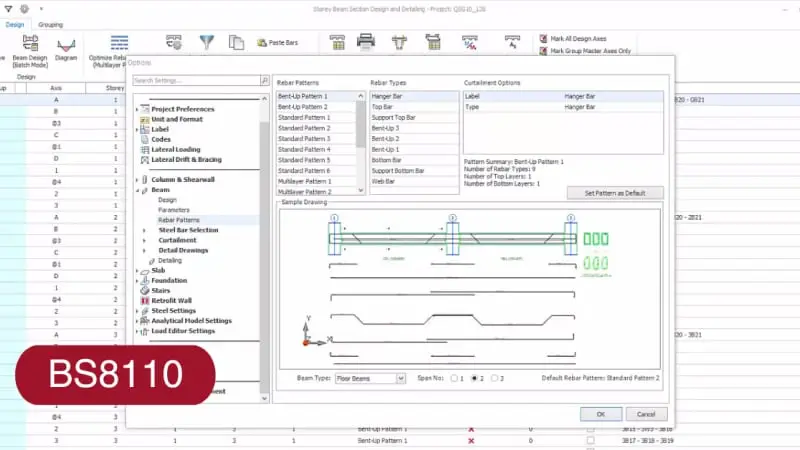
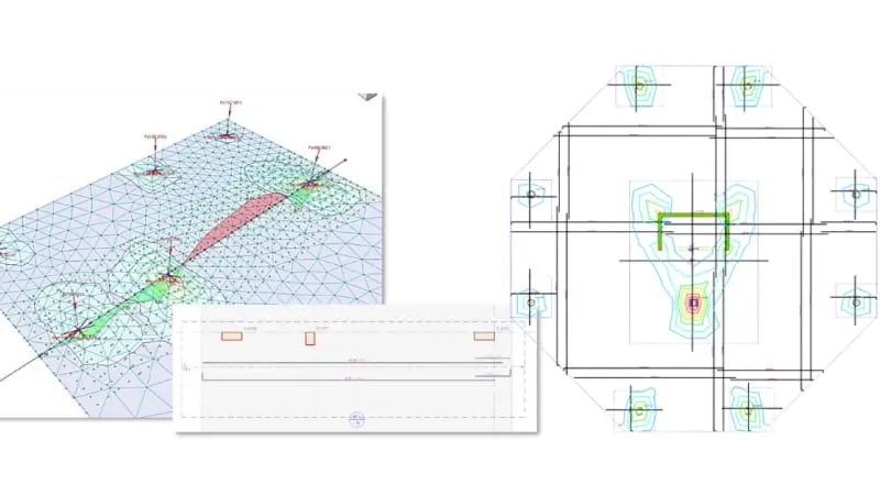
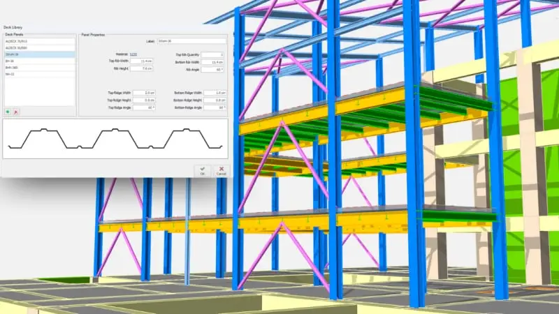
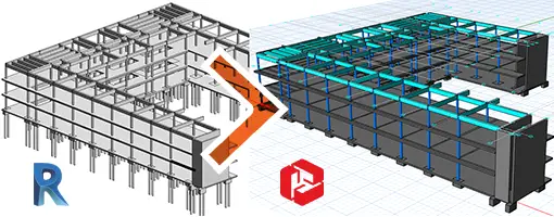
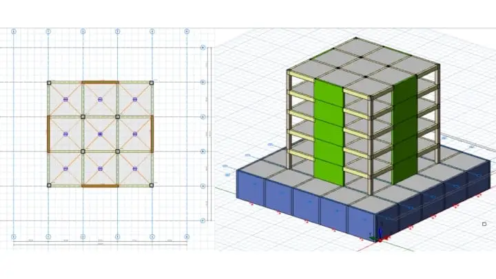
ProtaStructure enables you to easily design pad footings! Based on the results of Building Analysis, the forces and moments loaded on the columns, you can easily insert pad footings into your model, and quickly design each footing. Plus, you can obtain a detailed design report in a moment. In this document, you will find out all the necessary details about pad footing design, design flow and formulations utilized by ProtaStructure.
This document explains RC beam deflection design for rectangular and flanged sections. Calculation steps for immediate and long-term deflection are given with numerical examples based on the TS500 regulations.
ProtaStructure has bi-directional links between other industry-leading BIM platforms, and Autodesk Revit is one of them. In this document, you will get the essential details of the Revit integration of ProtaStructure, key aspects of the data transfer process, and necessary steps to follow for transferring a model from ProtaStructure to Autodesk Revit.
This document explains the analysis steps of the slab members according to TBDY 2018 Section 7.11 that should be checked in ProtaStructure under the impact of seismic force. Moreover, modeling steps, design requirements, reporting of analysis results and explanation for selected seismic codes are also included in this document.
The purpose of this document is to outline the steps to verify reinforced concrete column design using the capacity curve, or commonly referred to as N-M (Axial-Moment) Interactive Diagram. The N-M Interaction Diagram will be derived using empirical formulas of concrete stress block. This is then compared to the same capacity curve generated by ProtaStructure column design, to verify the validity and adequacy of its column design.
ProtaStructure provides calculations and calculation reports of wooden and metal formwork and formwork scaffolds now. In this document, the formwork and formwork scaffold calculations are explained through case studies for slabs, beams, columns, and shearwalls.
ProtaStructure designs columns bent about a single axis or bent about both axes according to the code clauses BS8110-1:1997: Part 1 Section 3.8 for British standards, by default. In this document, the process of column design according to BS8110 is explained. In addition, example cases are given for possible design choices and different methods described in the code.
ProtaStructure designs columnd bent about a single axis or bent about both axes using the code clauses given in BS EN 1992-1-1:2004 Part 1 for Eurocode, by default. In this document, the process of column design according to EC 2 is explained, and examples on the design of braced/unbraced square and circular columns are given.
In ProtaStructure, effective stiffness modifiers of the slabs could be adjusted for different analysis methods. One of the methods is using the “Finite Elements Floor Analysis” which considers the vertical load cases only independent of the building. The other method is “Finite Element Analysis” by using slabs in global building model for all load combinations.
In this document, a model is analyzed by using both methods, then the model is exported to SAP2000 and the results are compared.
This document explains how transfer beams are analyzed in 3D analysis softwares like ProtaStructure on a model. Results of building analysis are explained for front and rear transfer beam frames. Moreover, the results are compared to the ones obtained from traditional area tributary.
ProtaStructure can automatically generate the load combinations as required by different design codes. This document gives the load combinations according to different design and seismic codes, and also explains how to generate load combinations automatically using the Loading Generator.
ProtaStructure can determine the seismic separation condition according to ASCE 7-16 Clause 12.12.3. In this document, calculation details about seismic separation conditions are explained. In addition, the Seismic Joint Design user interface is introduced.
This document highlights general and project-based guidelines to model base isolators for seismically isolated buildings. Moreover, design requirements and reporting of the results are within the scope of this design guide, and some tips and recommendations for the selected seismic codes are also given.
ProtaStructure utilizes the Group-Sum methodology to calculate the total responses at the top and bottom of the shearwalls modeled with Finite Element(FE) shell elements. This document provides clearance and verification of shearwalls modeled with the FE shell elements, under various loading types.
ProtaDetails is capable of calculating lap and anchorage lengths according to several building codes around the world. This document presents detailed lap and anchorage length calculations for different building codes with case studies.
In this document, target displacement calculation for nonlinear pushover analysis according to FEMA 356 3.3.3.3.2 will be explained in detail and verified with the hand calculation.
This document will explain target displacement calculation for nonlinear pushover analysis according to EC8 Annex B in detail and verified with the hand calculation.
Traditionally, continuous beam lines are analysed and designed in isolation. The modelling of the support conditions in such cases is often unsophisticated or simplified. For example, in the analysis of secondary beams supported by primary beams, the traditional method is to perform 2 analyses independently & separately.
ProtaStructure checks global and local ductility conditions according to ACI 318 18.7.3. This document covers the calculation details of the strong column - weak beam condition checks.
ProtaStructure checks the beam-column joint shear limits according to ACI 318-19 Chapter 15 and 18.8.4. In this document, calculation details about beam-column joint shear are explained.
ProtaStructure checks the beam-column joint shear design considerations according to EC8 Chapters 5.5.2.3 and 5.5.3.3. In this document, calculation details about beam-column joint shear are explained.
ProtaStructure checks global and local ductility conditions according to EC8 Chapter 4.4.2.3. This document explains calculations for strong column weak beam condition checks.
Many structures will undergo a natural sway under purely vertical (gravity) loads. These sways can sometimes introduce significant changes to the expected moment diagrams in beams.
The axial force & moment of the columns and walls can also be significantly changed due to sway.
In such cases, it is important to ensure that checks are made for combinations where notional load cases are applied in sympathy with the natural sway of the structure.
ProtaStructure calculates non-structural member forces according to EC8 Chapter 4.3.5.
In the current document, calculations details about non-structural members earthquake force and parameters such as seismic coefficient are explained.
ProtaStructure calculates non-structural member forces according to ASCE- 7-16 Chapter 13.3.
In the current document, calculations details about non-structural members earthquake force and parameters such as seismic coefficient are explained
This design guide discusses the Beam Design to Eurocode 2 Design Code BS EN 1992-1-1:2004.
Users who wish to understand the analysis and design calculation for storey beams, are recommended to read this document.
This design guide discusses the Differential Axial Deformation Effect (DADE) of columns and walls due to 3D analysis of multi storey buildings.
The methods to reduce this effect using stiffness adjustment (Area Factor) & FE Floor Analysis are explored.
Users who find unexpected force diagram of a multi-storey building, especially bending moments in top storey beams, are recommended to read this document.
ProtaStructure’s punching shear check is an interactive design tool. You need to use it carefully on one column, or a group of the similar column(s) at a time to review/establish the correct design settings. Having done so rechecking can be carried out in a more automatic fashion.
In this design guide, we will show what this check can do for you, and illustrate the scope & limitations of which you need to be aware.
In this document, calculation and decomposition of loads on ribbed and waffle slabs are explained.
Modeling and design of ribbed and waffle slabs are out of the scope of this document.
In this document, pad footing design in accordance with TS500 is explained. An arbitrary pad footing is selected and it is designed under a single load combination.
Check this article on the sign of the results after response spectrum analysis and different options to work with them.
In this case study, the equivalent lateral forces acting on a 4 story residential reinforced concrete building is determined using the procedures described in International Building Code 2018 (IBC 2018).
In this case study, the equivalent lateral forces acting on a 4 story residential reinforced concrete building is determined using the procedures described in the 1997 Uniform Building Code (UBC 97).